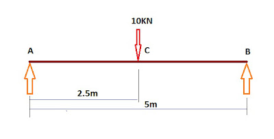
Here Below the Step by Step Procedure to draw Shear Force and Bending Moment Diagram of a Simply Supported Beam with a Point Load at Mid Span is Given :
Step 1 :- Calculation Of Reaction ==>
∑V=0
Therefore,
RA + RB – W = 0 or RA + RB = W or RA + RB = 10KN …….(i)
∑MB=0
Therefore,
+(RA*5) –(10*2.5) +(RB*0) = 0 or +(RA*5) –(10*2.5) = 0 or (RA*5) = (10*2.5) or RA = (10*2.5)/5
or RA = 25/5 or RA=5KN
Now putting the Value of RA in the equation(i) we get,
5 + RB = 10 or RB = 10-5 or RB=5KN
Therefore, RA=5 KN and RB=5KN
Step 2 :- Shear Force Calculation ==>
Shear Force at Point A(L) = 0KN
Shear Force at Point A(R) = 0+5 = 5KN
Shear Force at Point C(L) = 5KN
Shear Force at Point C(R) = 5-10 = -5KN
Shear Force at Point B(L) = -5KN
Shear Force at Point B(R) = -5+5 = 0KN
Step 3 :- Bending Moment Calculation ==>
Bending Moment about Point A = 0KN-m
Bending Moment about Point B = +(5*2.5) = 12.5KN-m
Bending Moment about Point A = +(5*5) –(10*2.5) = 25-25 = 0KN-m
Now Plot these Value in Paper in for making the required Diagram, to some suitable scale. It will look like the Below One.
Fill up the Diagram area with Hatch, I couldn’t give it due to Photoshop Problem.
For Details Of Reaction Calculation Concept Go To Link Below
Reaction Calculation Guide For Simply Supported Beam with Point Load


NEED SLOPE DEFLECTION MAX & CENTER DEFLECTION MAX STRESS