GPS For Surveying In Civil Engineering And Its Application

GPS For Surveying In Civil Engineering And Its Application

Field Surveying In Civil Engineering

What is GPS?

The Term GPS stands for Global Positioning System. The GPS is used to locate a location with the help of Latitude and Departure. with the help of GPS it’s possible to locate a point very precisely. GPS consist Of two main ends, the one is the Locating Sattelites and the other is the Receiver. Most of the people now a days are familier with GPS due to the huge use of Smart Phones.
The Global Positioning System was first evoled for the Defence of Countries, and it’s controlled from the California. It was used for locating various places which are important from the Defence point of view. Later on it was opened for public use. But the Same GPS System with more Powerful receivers it can be used in the Civil Engineering Field.

How GPS Works ?

A point is located with the 18 satellites which are orbiting around the Earth, 22,000 km above the surface of the Earth, these satellites are orbiting in 6 orbits, that means having 3 satellites in each orbit. And has a the capability to rotate a single time around Earth in 11 hours and 58 minutes. To locate a point two satellite is required, the more number of satellites are in use the more precision can be obtained.

Application Of GPS In Civil Engineering

Most of the Companies uses manual procedure of Surveying (i.e. Leveling, Contouring, Compass Surveying) to Prepare Contour Maps, Longitudinal Section Of Roads, Alignment of Roads, Bridges etc. But many Broad Companies in India and abroad uses GPS to locate  different points, preparing Contour maps, giving Alignments of Roads, Bridges where the p[precision is very essential or it may ruin the whole project for a simple error in surveying, on those places the survey work can be done with the help of Global Positioning System.

Advantages

  1. It helps to survey with many times greater Precision.
  2. It helps to complete a Survey with lesser time and thus helps to cut down the Completion Period.
  3. It Reduces the Difficulty of taking manual measurements to great extent.
  4. With GPS there is a very less chances of error. And this error may come only due to the Instrument malfunction.

Disadvantages

  1. The main Disadvantage is that, it requires high initial investments.
  2. To conduct such High End Survey works and to operate such Electronic Equipments much skilled persons are required.
Follow Techno Genome at :-

    Shear Force And Bending Moment Diagram For Simply Supported Beam

    Shear Force And Bending Moment Diagram For Simply Supported Beam

    Simply Supported Beam With Point Load At It's Mid Span

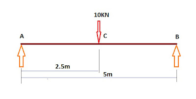
    Here Below the Step by Step Procedure to draw Shear Force and Bending Moment Diagram of a Simply Supported Beam with a Point Load at Mid Span is Given :
    Step 1 :- Calculation Of Reaction ==>

    V=0
    Therefore,
    RA + RB – W = 0 or RA + RB = W or RA + RB = 10KN …….(i)
    MB=0
    Therefore,
    +(RA*5) –(10*2.5) +(RB*0) = 0   or   +(RA*5) –(10*2.5) = 0  or  (RA*5) = (10*2.5) or RA = (10*2.5)/5
    or RA = 25/5  or RA=5KN
    Now putting the Value of RA in the equation(i) we get,
    5 + RB = 10 or RB = 10-5 or RB=5KN
    Therefore, RA=5 KN  and  RB=5KN


    Step 2 :- Shear Force Calculation ==>

    Shear Force at Point A(L) = 0KN

    Shear Force at Point A(R) = 0+5 = 5KN
    Shear Force at Point C(L) = 5KN
    Shear Force at Point C(R) = 5-10 = -5KN
    Shear Force at Point B(L) = -5KN
    Shear Force at Point B(R) = -5+5 = 0KN
    Step 3 :- Bending Moment Calculation ==>
    Bending Moment about Point A = 0KN-m
    Bending Moment about Point B = +(5*2.5) = 12.5KN-m
    Bending Moment about Point A = +(5*5) –(10*2.5) = 25-25 = 0KN-m

    Now Plot these Value in Paper in for making the required Diagram, to some suitable scale. It will look like the Below One.

    Shear Force And Bending Moment Diagram

    Fill up the Diagram area with Hatch, I couldn’t give it due to Photoshop Problem.

    For Details Of Reaction Calculation Concept Go To Link Below
    Reaction Calculation Guide For Simply Supported Beam with Point Load

    Follow Techno Genome at :-

    Support Reaction Calculation Guide For Simply supported Beam

    Support Reaction Calculation Guide For Simply supported Beam

    Simply Supported Beam With Point Load
    Here I will discuss about step by step Support Reaction Calculation Procedure. Say, there is a Simply Supported Beam with a Span Length Of L and Having a Point Load W at the Mid Span of the Beam. There are two supports A & B. The Reaction of Support A is RA and the Reaction of Support B is RB.
    Now, The whole lode is to be carried by the two supports, as the beam is symmetrical and carrying the point load at the mid span it is thus obvious the total load will be equally shared between two supports. So the The Support A will take Half of the Load ( i.e. W/2) and the Support B will also carry Half of the Load ( i.e. W/2). To make the Beam to stay in Equilibrium The Total Load The Beam is Carrying must be equal to The Total Reaction The Supports are Giving.Thus,
    RA + RB must be equal to W or RA + RB – W = 0. That means Sum of the Vertical Forces must be Equal to Zero, This the First Condition Of Equilibrium.
    Now Calculating the Moments, here the Third Condition of Equilibrium that algebraic Sum of the all Moments about a section must be equal to Zero.
    Taking Moment About B. Sign Conventions are, From Left to Right Clockwise Moment is taken as Positive and Anti-Clockwise Moment is taken as Negative.

    Now first Observe the Loads and Reactions. There is only a single load in the mid span. That means The Distance of the Point Load and the Support B is Half of the Span i.e. L/2. And there are Two Reactions, RA and RB at two supports. Now Starting from the Support A and going towards support B we find 3 Forces one after another in the following Order, RA, W and RB. Now Calculating the Moment about B :-

    +(RA*L) -(W*(L/2)) +(RB*0)= 0

    Now as the Distance between the Point B and the Line of Action of the force RB is 0, the moment generated due to the force RB about the Point B is is equal to Zero. Thus the equation becomes,

    +(RA*L) -(W*(L/2)) = 0  or  +(RA*L) = (W*(L/2))  or  RA = (W*(L/2))/L.
    Thus, we can find the RA, and as the whole load is carried by the the two supports, the value of RB will be,

    RB = Total Load – RA or RB = W – RA , or just simply put the value of RA in the first equation,           

    RA + RB – W = 0.

    The above Procedure is a general procedure to Calculate the Reactions for any type of point Loading on a Simply supported Beam.
    In the above case the reaction can be known easily as the Beam is carrying the point load at the mid span. The load sharing will be two equal half of the load on two supports, thus the Reactions will be equal to Half of the load at each of the supports.

    Follow Techno Genome at :-

    Civil Engineering Contracs Of Different Types

    Civil Engineering Contracs Of Different Types

    Contractor


    DIFFERENT TYPES OF CONTRACT===>

    1. Item Rate Contract.
    2. Percentage Rate Contract.
    3. Lump Sum Rate Contract.
    4. Labour Rate Supply Contract.
    5. Material Rate Supply Contract.
    6. Piece Rate Contract.
    7. Turn Key Contract.

    DESCRIPTION OF SOME IMPORTANT TYPES OF CONTRACTS===>

    Item Rate Contract :- 

    In this system of contracts  a contractor is required to quote rate of Individual Item of Works in Tender. This system of Contract is mainly done in Railway Department.
    Advantages:  a) Ring Formation  cannot be done.
                          b) Thorough analysis of rates can be done.
    Disadvantages:  a) The Comparative Statement cannot be made at the time of the opening of the 
                                  Tender.

    Percentage Rate Contract :-

    In this system of contract a contractor is required to quote the rate as Percentage above or Percentage Below or At Per with Rate Provided in the Tender by the Concerned Departments. This system is followed in all other government departments other than Railways.
    Advantages:  a) The Comparative Statement can be made at the time of the opening of the Tender.
                          b) The Total expenditure can be known before hand.
    Disadvantages: a) There are chances of Ring Formation.

    Lump Sum Contract :-

    In this system of contract a contractor is required to quote a fixed sum of money for the completion of a work completed in all respect according to the Specifications, Drawings and Designing provided in the Tender within the Completion Period.
    Advantages: a) The expenditure for a work can be known before hand.
                         b) No intermediate payment is to be done.
                         c) No problems of taking measurements.
                         d) The Contractor will have a erg to complete the work before time as the payment is  
                             made one time only after the completion of the work.
    Disadvantages: a) In this type of contract the intermediate progress of the work cannot be known.
                              b) in this type of contract it’s difficult to judge the quality of the work.
                              c) The Lump Sum Contract cannot be done for Repair and Maintenance Estimate.

    Follow Techno Genome at :-

    What Is Civil Work Tender Documents And Tender

    What Is Civil Work Tender Documents And Tender

    Contract


    TENDER ==> 

    The Tender is a written offering submitted by a Contractor in persuence of the notification by a concerned department. The Documents which are to be submitted by the contractor is supplied by the department to the eligible contractors on payment of usual cost. The Tender Form is tobe duly filled in and submitted in the Tender Box with locking arrangments in the room of the officer inviting the Tender in closed and sealed cover withinor on the Date and Hours of submission of the Tender specified in the N.I.T.

    TENDER DOCUMENTS  ===>  

    The various Terms and Conditions which are to be formulated while inviting a Tender for a Civil Works are as follows :-
    • A Notice Inviting Tender (N.I.T.) in the standard approved format of a Department.
    • A Tender Form with standard Conditions of Contract.
    • Quantity of Works which are tobe done and Materials, Tools and Plants (T & P) which are to be supplied by the Department if any.
    • Terms & Conditions.
    • Complete Sepecification of the Work.
    • Special Specifications and Additional Terms and Conditions.
    • One Set of complete approved Drawing of the work to be done.  

    The Contractor must sign each pages of the Tender Documents and necessary entries are made and a Forwarding Letter on the Letter Head of the Company Of the Contractor along with Bank Draft or any other form of Earnest Money are to be put inside a sealed and closed cover superscribing the Name of the Work and the Name of the Contractor.

    Follow Techno Genome at :-