Septic Tank Design Easily 5 Minutes

Septic Tank Design Easily 5 Minutes

Septic System Design or Septic Tanks Design can be done in various process, but most of them are critical and time taking laborious process. Here in this article I have given tutorial on how to design Septic Tank Easily within 5 minutes and Determine Septic Tank Size. Here I will also discuss some about the general Septic Tank Construction for designing of septic tank successfully you have to follow the steps given below one by one

Step 1: Calculation of Numbers of User : 

In any septic system design this is a very very important step as it will determine the total capacity of the septic tank required.This is the total numbers of user who will be using the septic tank within a single day. For the calculation purpose we must consider the maximum practical numbers of user who may use the W.C. within a day. The calculation can be done very easily, like suppose there is a 4 storied building and having two families on each floor. And each family contains on an average of 5 person. Therefore the building is accommodating (2 x 4) = 8 families and again 8 families will equal to users of (8 x 5) = 40 Nos. Users. Generally in no case user number is kept less than 20 users. Therefore here we will design a septic tank for 40 Users

Septic Tank Parts, Septic Tank
DIFFERENT PARTS OF A SEPTIC TANK

Step 2: Calculation of Liquid Volume in Septic Tank : 

In this step we will calculate the volume of waste liquid in septic tank which will occurs due to the use of 40 user. For normal detention period It is considered in designing purpose that a septic tank requires 0.085 cu.m. of space for waste liquid of each person per day is sufficient for design, keeping in mind septic tank cleaning which will be done periodically. also a future provision should be provided, which in general is considered as 25% of the actual volume required.
Therefore, Volume of Liquid @ 0.085 cu.m. per capita per day = 40×0.085 = 3.40 cu.m.
Allowing a future provision of 25% extra, therefore Total Volume of Liquid = 3.40+ 25% = 4.25 cu.m.

Step 3: Calculation of Internal Dimension Of Septic Tank :

Now we have to find out the internal depth, length and breadth of the septic tank. first of all we have to consider a liquid waste depth suitably from 1m to 2m for better efficiency. if the waste volume is large then we need to consider greater depth for making the length and breadth smaller to accommodate within the land. then as we know volume = length x breadth x depth (height), there for as we have already assumed the liquid depth so we can find the length and breadth by calculating the surface area of the liquid surface by dividing the waste volume with liquid depth
Now, considering a Liquid Depth of 1.20m.
Therefore, Surface Area of Liquid = (4.25/1.20) = 3.54 sq.m.
so now this 3.54 sq.m. = Length x Breadth. Now we can calculate the length and the breadth easily by either adopting a suitable breadth according to the land available or according to some proportions like considering the length of septic tank as the twice of its breadth, L=2B etc.
so we will have Area = Length x Breadth  
or 3.54 = L x B  
or 3.54 = 2B x B
or 2B^2 = 3.54
or B = Root of (3.54/2) = 1.33m say 1.40 m
Therefore, L = 2B = 2 x 1.40 = 2.80m, But more accurately the length shall be calculated like the following one, here L x B = 3.54 , now as we know the value of B therefore we can obtain the the value of Length by:
L x B = 3.54
or L x 1.40 = 3.54
or L = (3.54/1.40) = 2.53 m say 2.60m.
But there is another process which is suitable where there breadth is restricted, in those cases we have to limit the breadth by adopting a value, and then calculate the rest by the following :
Now, considering the Breadth of Septic Tank as 1.20m
 
Therefore,
Length x Breadth = 3.54 sq.m.
Or Length = (3.54/Breadth) = (3.54/1.20) = 2.95m , say 3m
Now this dimensions are must, but apart from this we have to provide a clear space above the liquid waste in septic tank so that the gas evolving from it can freely move and can escape through the vent pipe. For this reason we consider a gap above the liquid or free board of sufficient space, generally like the following:
Considering a Free Board over the Liquid surface of 300mm.
Therefore, Total Internal Depth of the Septic Tank will be = 1.20 + 0.30 = 1.50m.
 
Therefore, the Internal Dimensions of the Septic Tank are as follows :
 
Length = 2.60m      Breadth = 1.40 m    Height = 1.50m
 
Now prepare neat drawing of the above, below I have provided one, but the dimensions will not tally with the above one, it is just for reference.
 
Septic Tank Drawing, Septic Tank, Soak Pit Drawing, Soak Pit, Sectional Elevation of Septic Tank, Sectional Elevation of Soak Pit
SEPTIC TANK SECTIONAL ELEVATION WITH SOAK PIT
 
 
Keep visiting MyCivil – Civil Engineering Redefined for ore similar interesting Articles. Do Comment in this post and share it in your network if possible to help Techno Genome Grow.

If you like this Article then I am sure you will like the following well researched articles too, come on check them out also

Come Connect with me On Social Media

Septic Tank Design Easily 5 Minutes

Design Of Steel Beam Fastest Method With Example

Civil Engineering is vast field from Culverts to Dam , Buildings To Steel Bridges, so as so the Civil Engineering Materials, It includes Steel, Concrete, Timber, Aluminium, Glass etc. Steel Design is much easier in most of the cases than RCC Design in Structural Engineering. Civil Engineering Broadly has three main phase namely Planning – consisting of Drawing, Estimating etc. Structural Engineering Design consisting of Analysis of Structures and Design Of Structures and last of all Execution which means erecting the actual work according to the Planning and Designing. Structural Engineering has always been a field of respect amongst all the Civil Engineers. Today I will discuss about a part of Structural Engineering which will be dedicated toward the Design of Steel Beam specifically Steel I Beam. After reading this article you will be able to design a steel beam by your own without any problem. To make the explanation easy for understanding I will elaborate a simple yet considerably good problem which will cover all your needs as far as the Civil Engineering and Structural Design is concerned. I know now a days all the Structural Engineering Analysis and Design is being done by Computer Software like STAAD Pro, Ansys and all that, but without having the knowledge of manual Design of civil and structural engineering all those are useless because you will be not able to understand the Design Data and the outcome from the software.
But before going to start You need to understand few things which I should tell you first or at the later stage you may find some problem.


What is a Structural Engineer and Job Profile :- 

Civil Engineering as you already know is a vast field with full of opportunities, there are every aspect of civilization which is either directly or indirectly elated and proportional with the growth of the civil engineering field itself. Civil Engineering mainly deals with the few categories of engineers who take cares of different things, like Structural Engineer who deals with the all civil engineering structural design and analysis works for the safety and stability of the structure. Another important filed very close to Structural Engineering is Geotechnical Engineering which deals with the all about soil and its data collections tests bearing capacity determinations etc. And there is also Construction Engineers who do the actual construction on the field. In civil engineering structural engineer generally performs the structural design of Beams columns foundations slabs and other structural components, and also does the analysis jobs of an existing structure for determining its ability to carry loafs that it has been designed for. These Structural Engineer are well recognized among all the other fields of civil engineering. Structural Engineer and there jobs are mainly outsourced to a third party structural engineering firms in most cases.

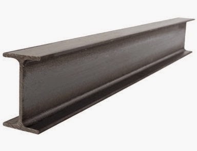
As a Civil Construction material steel was vastly used in early days for building works and in cases where the loads are heavy but now a days most of the buildings are made of RCC however Steel is used in the places like Steel Bridge Design, Railways, Docks , Over bridges and etc. places where the loads are very heavy because the Bearing and Shearing capabilities of Steel is more than Concrete. And many a buildings in places like United Kingdom, United States, Australia and many other modern countries Slab Beam and Column Design are still being done with Steel as a Civil Construction material. Steel which are used in structural design as a construction material are used in the form of Rolled Steel Sections of different shapes like I Sections, Channels, Tubes, and also in built up sections. For Design of Steel beam mainly I sections are used. Now remember that great equation of the Theory of Bending which is (M/I) = (f/y) = (E/R) , I know you can steel recall this don’t you?. Okay let us just recap it in an easy way, in this equation the denotations are as follows :-

M = Bending Moment Acting on the Beam due to loads
I = Moment of Inertia of the Beam section
f = Bending Stress in the Steel Beam
y = Distance between the any fibre of section and the Neutral Axis [For getting maximum Bending Stress the value of y must be maximum as the Bending Stress is directly proportional to the distance between fibre at a point and the Neutral Axis, hence we need to consider extreme fibre which gives maximum value of ‘y’, this equals to h/2 where h is the depth of section, as the Neutral Axis of symmetrical sections like I-Section will fall at its C.G.]
E = Modulus of Elasticity of the Beam section
R = Radius of Curvature of the Shape of Bending of the Beam
 
But we won’t be needing all these, we just need the (M/I) =(f/y) for the design of steel beam.
Now we can rewrite the equation (M/I) =(f/y)  as (M/f) = (i/y) can we? Yes we surely can by cross multiplication. Here the term obtained (i/y) is known as Section Modulus and this is a very important factor because upon it the strength of any section depends. Actually When the Maximum distance between Neutral Axis and the fibre is considered, that is the distance between the Neutral Axis and the extreme fibre, meaning the maximum value of ‘y’, This term (i/ymax) or Section Modulus is denoted with ‘Z’ , therefore Z=(i/ymax) . I hope up to this level you have understood, and these things you have already studied in structural analysis isn’t it? Yes you have for sure. So basically in a Structural Steel Design of Beam we will design the beam for flexur, that is for Maximum Bending Moment and then chose a suitable Beam section from the list of available sections which varies from country to country and this list can obtained from bureau of standards of your country. And after choosing that section then we will check for other factors like Shear Stress, Deflection and look if that section can stand safely. That’s all isn’t it simple? Okay now lets get started, I will discuss How to Design a Steel Beam in Step By Step that You cannot escape without Understanding.
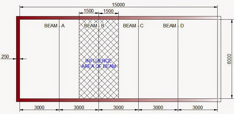
Let us consider a problem for explanation, suppose there is a hall room measuring 15m X 6m inside and the walls are 250mm thick. And it is given or you have thought to provide beams at a centre to centre distance of 3m apart. The beams are supporting a R.C.C. roof slab of 150mm thick with finishing on it, the flanges being restrained on slab. The Hall is a commercial type building. So let us design these beams.


Step 1 – Preparing a Neat Sketch from the Problem For Steel Beam Design :-

This is important in all types of Civil Engineering Structural Design Problem. As You know Drawing is the Language of Engineers and Line is the Language of Drawing, so prepare a neat drawing after reading the problem and give all the dimensions possible in the drawing. A Drawing is a must and it must be 100% correct as all the designing will be dependent upon this drawing. So prepare the drawing with caution. Here I’ve prepared one, now study it thoroughly, What Data you are getting? Yes the inside dimensions of the room that is 15m X 6m, This thickness of the wall which will act as the bearing of the beam are 250mm thick, and the Centre to Centre distance between the beam that is 3m.
 
Beam Layout
STEEL BEAM PLAN


Step 2 – Calculation of the Influence Area of the Structural Steel Beam :-

The Influence Area of a Beam means the area of which the loads are acting that beam, or simply you can say that the beams have to be designed for the loads on that area that is the influence are. Here in this particular problem we see that all the beams are in a similar situation, that means they are within a same room and same direction, they are supporting the same roof with same finishing, and these beams are spaced at a same distance, that means the condition of all these beams are identical to each other, so we will do structural design for any one of the beams and that design will be fit for other beams. If the conditions were not identical then we have to design each of them individually for economy or we have to design the beam which is having the greatest load on it. Let us consider the Beam B for Design
Here all beams are 3m apart C/C distance from each other, hence a single beam B is having Beam A on the left at 3m distance apart and Beam C on the right side is also 3m apart, so the Beam B is supporting half of the load of the area between Beam B and Beam A on the left side and on the right side the Beam B is supporting half of the load of the area between Beam B and Beam C. Hence it means on the left side supporting a strip of (3/2) = 1.5m width and on the right side again supporting a strip of (3/2) = 1.5m width. So the influence area becomes a strip of width 1.5m + 1.5 m = 3m and its length being from centre to centre of the bearing at the each end of the Beam that is the Effective Length of the Beam.


Steel Beam, I Section
STEEL BEAM I – SECTION


Step 3 – Calculation Of Loads acting on the Steel Beam :-

Now we have to calculate the loads acting on that influence area as calculated above as Civil Engineering Structural Design will be based on these Loads. These loads can be broadly classified as Dead Loads and Live Loads. Dad loads means the loads coming from all unmovable Objects like Slab, Beam itself, Flooring etc. and Live Loads Means the load coming due to the movable objects such as we humans, furniture and other movable loads. Generally Dead Loads are calculated and Live Loads are specified according to the Type of the structure, varying in intensities with different types. Like for residential building generally it is 2 KN/ m2 and for Commercial Building it is 4 KN/m2. The Dead Loads which are to be calculated are as follows:-
Dead Loads –  1) Self weight of beam(Assumed 1KN per m)
2) Load of slab supported @25 KN /m3 for R.C.C.
3) Load of floor finishing (generally 0.5KN/m2)
4) Load of Brickwork if any @19.2 KN/m3
All the loads are to be calculated on per m run basis so that it becomes a U.D.L. The total load acting on the beam will be  the sum of the Dead Loads and Live Loads
Therefore, Total Load per metre run, w = Dead Loads + Live Loads
Here in this case the load calculation will be as follows : 


A) Dead Loads –

                                I.            Due to the self weight of the beam – 1 KN/m
                              II.            Due to the 150mm thick slab = (1 x 3 x 0.15) x 25 = 11.25 KN/m                                       that is [Length x Breadth x Thickness] x Density
                            III.            Due to Floor Finishing @ 0.5 KN/m2 = (1 x 3) x 0.5 = 1.5 KN/m                                   that is [Length x Breadth] x Load Intensity  
B)Live Load – @ 4 KN/m2 = (1 x 3) x 4 = 12 KN/m  [Length x Breadth] x Load Intensity
Therefore, Total Load per metre run, w = (1 + 11.25 + 1.5) +12 = 13.75 + 12 = 25.75 KN/m
 

Step 4 – Calculation of Effective Length Steel Beam :-

It is taken as the length between the centre of bearings of the beam at each end.
Therefore in our case having a clear span of 6m and 250mm support at each end by means of wall we get,
Effective length, l = 6 + (0.25/2) + (0.25/2) = 6+0.125+0.125 = 6.25m


Step 5 – Calculation of Maximum Bending Moment On The Steel Beam :-

Here we will introduce the Structural Steel Beam Design Formulae for the first time. Now calculate the maximum bending moment acting on the beam by adopting suitable formula which are as follows :-
i)                    For point load at the mid span of the beam: –  M = (w.l/4)
ii)                  For U.D.L. Throughout the span of the beam :- M= (w.l2/8)
iii)                For Point load at any point of beam :-  M = (w.a.b/l)
For any unusual loading you have to calculate the maximum bending moment and shear force by shear force bending moment diagram drawing procedure.
Here in this case as we are having a U.D.L. of 25.75 KN/m throughout the span hence we will use the second formula that is M = (w.l2/8)
Therefore, in our problem we get,
Maximum Bending Moment, M = (w.l2/8) = ((25.75 x 6.252)/8) = 125.73 KN-m
= 125.73 x1000 x 1000 N-mm = 125730000 N-mm


Step 6 – Calculation of Section Modulus Required For Steel I Beam :-

Here we will use another Civil and Structural Engineering Design Formula  for steel beam design. Here we will determine the Section Modulus required in order to resist the Maximum Bending Moment acting on the beam. At the star of this article we had found that (M/I) = (f/y) or (M/f) = (i/y) again Z=(i/ymax) therefore we can rewrite it as Z=(M/f). The value of ‘f’ depends upon the grade of steel and factor of safety. Considering Fe250 Grade of steel, and according to code of practice of the different country the factor safety will vary for obtaining the permissible stress (f) from the Yield Strength of Steel. Here I will follow the IS 800 Code and according to it Maximum Permissible Stress = 0.66 X Yield Strength. But in case of I beam and channel with equal flanges the permissible bending compressive stress shall be calculated from the table given in the code by knowing the value of ((D/T)/(l/ryy)) where,
D = Overall depth of the beam

T = Mean thickness of gthe compression flange, which equals to the area of horizontal portion of flange divided by width
l = Effective length of compression flange
ryy = Radius of gyration of section about its axis of minimum strength (y-y axis)
However the value of permissible compressive stress shall never exceed 0.66fy, where fy = Yield Strength of Steel. Here for easy understanding considering that the permissible compressive stress has got the same value that of 0.66fy.
in case of Fe250 the Yield Strength is 250 N/mm2, Hence Maximum Permissible Stress, f = 0.66 x 250 = 165 N/mm2.
Thus returning to our problem we get that,
Zrequired = (M/f) = (125730000/165) = 762000 mm3       [Unit Derivation,  Z = (i/ymax) = (mm4/mm) = mm3]
For  selecting a suitable section from the steel table that is the chart of Rolled Steel Section we have to get the value in terms of cm3, Hence 762000 mm3 = (762000/(10x10x10)) = 762 cm3


Step 7 – Steel I Beam Selection of Suitable Section from Steel Table :-

Now we have to use the steel table which has the standard Rolled Steel Section List and their properties written on. These Tables are country specific and will vary from United Kingdom to United States to Australia to India. So you need to use your country specific steel table. We have to choose a section, preferably a I Section from the Steel Table, which will have a Section Modulus (use section modulus about –x-x axis)  or ‘Z’ equal to or greater than what is found to be required (Zrequired), and also have to note all necessary properties of that Steel Section. In our case I will use SP-6 Steel Table, and I have found the following section to be suitable in case of our Civil Engineering Design Problem:-
Let us Try ISMB 350 @52.4 kg/m Having the following properties,
Sectional Area, a =66.71 cm2
Depth of Section, h = 350mm
Thickness of Web, tw = 8.1mm
Moment of Inertia, Ixx = 13630.3cm4
Section Modulus, Zxx = 778.9 cm3


Step 8 – Check For Shear Of Steel Beam :-

As of now we have made a design based on flexural strength that is based on Maximum Bending Moment, and selected such a section which will be safe in Bending. Now we have to check if that section will be safe in shear or not. For this we have to calculate the Maximum Shear Force acting on the beam, as for U.D.L. this can be calculated by using the Structural Engineering Analysis Formula V=(w.l/2) , where,
V = Maximum Shear Force
w = Load per metre run
l = Effective Length of the Beam
Then by this shear force we have to calculate the average shear stress on the beam due to the Maximum Shear Force, by using the formula Tva = (V/h.tw), After getting this Average Shear Stress we have to calculate the permissible Shear Stress which depends upon the grade of steel and also upon the factor of safety which is varying according to Code of Practice of different country, according to IS 800 Permissible Shear Stress = 0.4 x Yield Strength of Steel, Hence for Fe250 Grade Steel we get, Permissible Shear Stress, Tvm = 0.4 x 250 = 100 N/mm2. Now if the permissible stress is greater than or equal to that of the Average Shear Stress on Beam then the Section is Safe In Shear, or else it is unsafe therefore, we have to select the next higher section in terms of Section Modulus and area of Web (h.tw) and give trial for shear check, until it becomes safe.
In Our case of problem it will be as follows :-
Maximum Shear Force, V = (w.l/2) = ((25.75 x 6.25)/2) = 80.45 KN = 80450 N
Average Shear Stress in Beam, Tva = (V/h.tw) = (80450/(350 x 8.1)) = 28.38 N/mm2 < 100 N/mm2
Hence the section is Safe In Shear.
Steel Column Beam Connenction
STEEL COLUMN BEAM CONNECTION


Step 9 – Check for Deflection Of Steel Beam :-

We are almost done in the Design of Steel Beam, this the last check we have to perform, the rule is same, if the section satisfies the check then it is safe, or otherwise we have to check with another section having more depth (h). For this check we have to calculate the Actual Deflection on the beam by using the Structural Analysis Formula in case of U.D.L. the formula is  :-
Del(Symbolic) = (5/384) x (W.l3/E.I)
Where,
Del = Deflection in cm
W = Total Load = w.l in N
E = Modulus of Elasticity, For Steel E = 2 x 10⁵ N/cm2
l = Effective Length in cm         [ Small L]
I = Moment of Inertia in cm4   [Notation = Capital Eye]
And Permissible Deflection = l/300
Here, In the case of our problem the calculations will be as follows :-
W = Total Load = w.l = 25.75 x 6.25 = 160.94 KN = 160940 N
E = 2 x 10⁷ N/cm2
l = 6.25 m = 625 cm
I = 13630.3 cm4
Actual Deflection, Del = (5/384) x (W.l3/E.I) = (5/384) X ((160940 X 6253)/((2×107) X 13630.3)) = 1.877 cm
Permissible Deflection = l/300 = 625/300 = 2.083 cm > Actual Deflection, Hence Safe.
Therefore The Section selected by us is Safe in All Respects.
Therefore Let Us Provide ISMB 350 @ 52.4 kg/m


Apart from these checks there are also other checks like, Check for Vertical Buckling [Important for Point Loads], Check for Direct Compression in Web, Check for Diagonal Buckling.This check procedure have not been included in this article now, but will be Updated Soon.
For making this Article Universal I’ve used only Common Terms and Denotations which are well known in all of the Countries Like United Kingdom, United States, Australia, India and other places, as the Denotations may vary Code to Code of Different Countries.

 
Now the Structural Design of Steel Beam has successfully completed in all respect. I hope You understood all along with ease, I’ve made it as much as easy as possible. Do Share the Link of this Article On Your Network Of People of All Fellow Civil Engineers and Your Social Network as a Token for Appreciation of this Article if this Article Helped You in Understanding.Keep Visiting MyCivil- Civil Engineering Redefined for more Articles at www.mycivil.engineer. Please do comment on this post, as your comments are very important to me so that I can understand if you are having any problem, and also it will be helpful for others who will visit this Blog. Join This Blog for Regular Updates and also you can now follow us in the Facebook, Twitter and also on LinkedIN. 
 

If you like this Article then I am sure you will like the following well researched articles too, come on check them out also

Come Connect with me On Social Media

Septic Tank Design Easily 5 Minutes

Field Quality Control of Concrete and Deadly 5 Mistakes

What is Quality Control of Concrete ? What is Controlled Concrete ? How the the concrete should be mixed in Concrete Mixer ? . In the Construction Engineering The Top 5 Constructional Mistakes and Concrete Problems which can bring disastrous results if ignored are not the huge ones but very common in every construction work, which gets out of the notice of the Engineer-In-Charge in most of the cases. As I feel most of the bad construction takes places not due to the unwillingness of the Engineers, but mostly due to the lack of awareness about those small things which they take lightly and thinks they are of no major importance and will not affect the ultimate construction. I do partially agree with them to the fact that it will not harm the ultimate construction. But How long? How long that improperly made structure be durable and sustainable to the causes of failures? Though this constructional errors may not hamper it all or partially the structure in short run, say about for 10 to 15 years after the construction but in the long run it will cost a massive amount for its restoration due to the degradation through which it will undergo in the future. No one of us like You and me would like to construct a permanent structure which only lasts for 15 years safely, do we? So for assuring the safety to the structure, its durability to withstand all probable condition in future and for preventing the costly restoration works we must take care strictly to the following things, which in general larger part of us don’t really bother about. Here I will discuss about those Top mighty mistakes and their consequences if not corrected at the time of occurring as Quality Control of Concrete is foremost important both in Controlled or uncontrolled concrete production.

1) Clear Cover Of Column, Beam and Slab :-

Clear Cover means the clear distance between the exterior face of the reinforcements towards the nearest surface of the RCC Section and the exterior face of that section. In most of the general cases the values of clear cover are 50mm for Foundation, 40mm for Column, 25mm for Beam, 15mm for Slab and Stair.
Now I’ve seen In most cases that people tend to ignore this cover value about weather it is maintained correctly or not, in cases I found that there may be unequal cover provided on column sides like in one side mason has given 20mm cover and on the other side it is 75mm. This occurs mainly due to the not properly using Cover Blocks for maintain the cover. In case of Beam, Slab the same thing occurs, the mason either may have increased the cover or may have decreased the value than what is actually to be provided. In either way it’s harmful and may bring catastrophic results.
Concrete Spalling
EFFECT OF MOISTURE PENETRATION

As a result of the of the above the consequence will follow like this way, if we provide insufficient cover then after 5-15 years later depending upon the exposure the insufficient cover will be easily penetrated by the moisture as the cover is insufficient to resist the penetration and also due to the fact that if cover is too little then the concrete cover at the face of reinforcement will be so thin that it will have a tendency to crack and hence will ease the entrance of moisture, which in turn will corrode the reinforcement then the structure will lose it’s capacity of taking loads as rusting in the Steel is made of loose particles hence the Bond between the steel and the concrete will be totally lost, and  will cause a failure of the structure under the Load. If the cover is increased than what has been specified by the Designing sheets then there will lie a huge risk of flexural failure of the structure due to the fact if the cover is increased then it means the effective depth of the structure will be decreased also, due to this decrease in the effective depth in the section, the Moment of Resistance of the section will get reduced drastically even with a small increase in the cover than what is specified. Therefore the structure will not be capable of taking up the Designed Bending Moment. So we now see that the ignorance of the cover must be avoided, and the specified cover in the designing sheet must be strictly followed to.

2) Addition Of Extra Water For Better Workability :-

This is one of the biggest silly mistake that sometime happens. This specially takes place in areas where weather is Hot, and the Water from the Green Concrete (Fresh Concrete) is evaporating at a very fast rate. In those conditions Fresh Concrete becomes dry and less workable and harsh. For this reason it becomes very difficult to place the concrete and compact it properly, and as a cure to this many a people adds water to the concrete to make it workable again. This will cause catastrophic results, as addition of further water to the concrete will change the Water-Cement Ratio of the concrete, and the increase in the Water-Cement Ration beyond what is specified for that particular mix will reduce the strength as we know from the Abrams Law of Water-Cement Ratio that The Strength of Concrete is Inversely Proportional to the Water-Cement Ration of Concrete Mix, other factors remaining constant. Therefore this addition of water for the sake of improving the workability will not improve the quality of concrete, rather it will destroy it absolutely.

It is my earnest requests to everyone please don’t do this, please don’t let others to do this also in front of you. I know how hard it is concreting in the hot zone due to the rapid evaporation of moisture from the Fresh Concrete, but we can steel make it our way, Don’t We? We can use Admixture to solve this. Water Reducers can be used as Admixture, like PCE that is Poly Carboxylic Ether. But dosing must be carefully done or all the concrete will become useless mass. Now You may say that for small constructions like Residential Buildings, other small castings where Admixtures may not be available, then What to do there? This can be solved by synchronizing the rate of production of concrete with the rate of placement of concrete. Don’t make concrete of too much quantity that it cannot be used at that rate, hence there is being stored a heap of concrete which is taking time to be consumed on and dries up. Match the rate of production with the rate of consumption and keep the mixing plant as close as possible to the spot of placing of concrete. In this way you will surely be able to solve out the problem of drying out of fresh concrete and becoming it less workable.

3) Free Fall Of Concrete :-

Concrete is the conglomeration of Binding Material (Cement), Fine Aggregate (Sand), Coarse Aggregate (Stone Chips) with right proportion of water based on the Water-Cement Ratio. As the Specific Gravity of different ingredients of concrete varies hence when concrete is dropped at the time of placing of concrete the different ingredients tends to fall at different rate under the action of Gravitational Pull. Therefore all the ingredients has a tendency to get separated from each other, but if the fall of concrete is not from much height then these ingredients does not get separated from each other due to the binding of cement paste. But if the Concrete is dropped from a greater height then the cement paste fails to hold them as a homogeneous mixture and all the ingredients separates and gets deposited in layers according to their specific gravity, hence the Stone Chips silts at the bottom, then over it sand silts then over it cement slurry of the greater portion.
Segregation Of Concrete
CONCRETE SEGREGATION

This phenomenon is known as the Segregation of Concrete. Therefore in this case the concrete does not remains actually concrete, and losses almost its all properties and strength, and such a structure collapses under Design Load. This can be prevented by dropping the concrete from a maximum height of 1.5m. I’ve seen in casting of column, many people are casting the full length of column at a time, which means a full length of column say about 2.7m is being caste at a time, hence the concrete dropping from the top is falling through a height of more than 1.5m, as a result segregation takes place at the bottom of the column, and the whole column becomes unstable under the loads and have greater chance of collapsing. And one more thing, Patching up the segregated column with Rich Mortar say of proportion 1:3 will not cure it, this patch will only hide the Scar beneath. Only cure is to dismantle the column and reconstructing it.

4) Improper Compaction :-

Compaction is a very essential process in concreting practice. Proper compaction makes a concrete dense, and hence the harden concrete results in having greater density which in turn gives higher durability to the concrete, making it impervious to moisture and other harmful chemicals. As the density increases with good quality compaction hence it gives greater strength, and also the honeycombing can be avoided.
Honey Combing Of Concrete
HONEY COMBING DUE TO BAD COMPACTION

If Compactions is not good then durability of the concrete will be reduced and also strength will be reduced. Improper Compaction causes air voids in the concrete which reduces the strength of the concrete. Only About 5% Voids can reduce the strength of the concrete up to 30%. Hence this becomes very necessary to do proper compaction to the concrete. The Concrete in Beam, Lintel and in other type of section where Depth is 150mm or more in those cases Concrete should be placed in layer and after compaction of a layer the next layer should be laid and the compaction should be done and then the next layer and compaction again so as to achieve a Compact and Homogeneous Concrete.

5) Too Early Removal Of Formworks :-

This is another thing which is being done all around mostly in case of the construction of Residential Complexes. A concrete structure gains strength with age, and the design strength which we target for is achieved at 28 days. So logically a structure should be given support by means of props for full period of 28 days, but the fact is that after a structure is ready and has gained its design strength even then at that time it is not subjected to full design load as the whole structures including finishing works cannot be complete within that period and hence we can flexibly remove the props when a structure gains about 70% – 80% of the design strength. This much strength is generally gained at 7 Days, but before this the props must not be removed. As for this reason the minimum period for which props are to be provided is 7 days, no matter how short is the span and how unimportant it is. But in actual practice the Time frame for which support of the props are to be provided depends upon the type of structure and the span of it. Generally For Slabs props must be provided for 7 Days in case where the span is up to 4.5m and for span over 4.5m the time of supporting is 14 Days. In case of Beam for span up to 6m the time for which props are to be provided is 14 Days and for span over 6m the time for supporting is 21 Days. For all the structures the side shuttering may be removed after 16 hours – 24 hours.

So the main problem in removal the formworks early is that the structure will not have enough strength to resist the design loads which will then cause failure of the structure.
I hope You have enjoyed this article, I will be posting on my next article about Common mistakes made in Brickwork. If you feel this article is useful then do share the link of this post in your network. Join Techno Genome Today for the Growth of this Blog, make it large “For Us For Them”. Any Comment will be Highly Appreciated. Keep Visiting MyCivil – Civil Engineering Redefined for More Articles which may change your Thought @ www.mycivil.engineer .


If you like this Article then I am sure you will like the following well researched articles too, come on check them out also

Come Connect with me On Social Media

Septic Tank Design Easily 5 Minutes

Field Tests Of Building Materials

Field test of brick, cement, sand and stone chips are very much essential as they are the most common construction materials which are used in almost all of the civil engineering construction from brickwork to floor finishing everywhere. As a civil engineer, working in a site is the challenging one, as on the site engineer all the responsibility and liabilities depends upon for good quality construction.  But alone a good supervision is not enough for a good construction having required properties and durability. A proper quality control is essential at all the stages, specially at the very start , where we have to select right materials for a type of construction, as the materials are the cell of each structure. A Civil Engineer may not always have the facility of laboratory at the site for the testing of materials so as to ascertain the quality of a material weather it is bad or good, suitable or not. So a civil engineer should be able to judge the quality of the basic construction materials such as Brick, Cement, Sand and Stone Chips by means of Visual Inspection of those materials, which can be done by doing the Field Test on those materials. Here I’ve listed the different field tests for basic construction materials which becomes necessary in day to day work.


How To Check If A Brick Is Good? ==>

Brick Stack
BRICK STACK


The following field tests are to be performed in order to determine if a Brick is good :-

  1. A good brick should be of proper shape and standard specified size, the edges of it should be sharp, there should not be any cracks and fissures on the brick. 
  2. The colour of a good brick should be copper red colour. A yellowish tint on brick indicates that it is under burnt and hence possessing of lower strength, and if a brick is of dark blackish blue colour then it indicates the brick is over burnt and is brittle in nature. 
  3. When a brick is struck by a hammer or against another brick, it should emit a clear metallic ringing sound, it should not be dull. 
  4. A freshly fractured brick should show a homogeneous compact structure without any lumps. 
  5. If a brick is dropped from about a height of 1m on a hard ground or on another brick, it should not break. 
  6. When a brick is scratched with finger nail it should not leave any impression on the brick. 
  7. A good brick (1st Class) should not absorb water by not more than 20% of its own Dry weight when immersed in water for a period of 24 Hours.

How To Check If Cement Is Good? ==>

Cement Test
CEMENT STACK
 
The following field tests should be performed to determine if the cement is of good quality :-
  1. The cement should be of Greenish Gray colour for Ordinary Portland Cement, and Blackish Gray colour for Portland Pozzulana Cement and Whitish Gray colour for Portland Slag Cement.
  2.  There should not be any hard lumps on cement, the cement should be finely powdered. If cement contains hard lumps, then it must be rejected. 
  3. The cement when rubbed between fingers should feel smooth, it should not feel granular. If it is granular then it means adulteration with sand. 
  4. A cement paste should feel sticky in between fingers. 
  5. When hand is dipped into a heap or into a bag of cement, it should feel cool, not warm. 
  6. If a hand full of cement is thrown into a bucket of water, the cement should sink, not float as the Specific Gravity of Cement is greater than that of Water. 
  7. If a thick cement paste made on a glass and immersed in water should set, not crack.


How To Check If  Sand Is Good? ==>

Good Quality Sand
GOLDEN YELLOW SAND, A SIGN OF GOOD QUALITY SAND


The following tests should be performed to determine the quality of Sand :-
  1. The Sand should be free from organic impurities and mineral salts, The maximum permissible quantity of organic impurities should be restricted to 5%. 
  2. The Sand should be of Golden Yellow colour. 
  3. The Sand particles should be sharp and angular to increase the interlocking property between the sand particles. 
  4. The sand should coarse for Concreting and medium sand may be allowed in brickwork and is preferable for plastering works.
 

How To Check If Stone Chips Are Good? ==>

 
Stone Chips Stack
STONE CHIPS STACK
The visual tests or field tests for Coarse aggregate, that is stone chips are very limited though there are many laboratory tests are available. Mainly the following things are observed as for Field Test :-
  1. The Stone Chips are to be well graded to increase the mechanical interlocking between them. 
  2. Stone Chips should be Angular as far as possible and be porous. 
  3. The Stone Chips should not be flaky and elongated. 
  4. The Stone Chips should not contain organic and other impurities, as only 5% clay content in concrete can reduce the strength of the concrete as much as 20%.
 
 
I hope this article will help you in your day to day work, as a Civil Engineer I feel these small little things are very much important as a good material is inevitably necessary to produce good construction. Taking care of these small things can turn out great results, which otherwise may not be achieved by higher designing standards. Quality control is the key to the construction, as the Ingredient of good quality will surely produce better taste isn’t it?.

In my next article I will discuss about the Top 10 Faults which are done by mason, and which are mostly ignored by the engineers but which may cause disastrous results in the ultimate structure.
Any comments will be highly appreciated, and praying to all of you to share this page link in your network to spread this words, as it is very important from all of us, and Being a Civil Engineer it is our responsibility to construct a structure which are safe and also durable without compromising. Join Techno Genome if you like this article as your presence is the Key Strength of Techno Genome. Keep Visiting MyCivil – Civil Engineering Redefined at MyCivil.engineer. you can find me in Facebook Techno Genome Page and at Twitter, and can connect me at LinkedIN also.


If you like this Article then I am sure you will like the following well researched articles too, come on check them out also

Come Connect with me On Social Media

Septic Tank Design Easily 5 Minutes

Prestressed Concrete Structures A Brief Description With Example

Prestressed Concrete Structure is the one of the most advancement in the Civil Engineering Construction Field, particularly in the Concreting Operation. In the modern day every heavily loaded structures such as Bridges, Flyovers, Railway Sleepers in all these structure where loads are so heavy that Normal RCC will not be enough there prestressed concrete is used. In this article I will share with you the main concept that is the backbone of the Prestressing technique and procedure for the Industrial manufacturing of Prestressed concrete, also after reading this article thoroughly you will understand why one should resort to Prestressed concrete, Advantages of Prestressed concrete over the normal RCC structure. First of all let us understand what the science is being the backbone of this prestressed concrete structures.

 
Prestressed Concrete Working Principle
PRE STRESSING ACTION TO COUNTERACT THE TENSILE STRESSES
 

Why Prestressed Concrete Structures becomes necessary ==>

As you and me already know that a structure under the action of different loads acting on it, the structure takes the shape of bending. The loads acting on a structure causes it to bend in between the supports with shape having convexity downwards that is what we called as positive bending,  and near the support the bending occurs in a reverse shape , that is the convexity is on a upward direction, this we called as the negative bending of the structure. Now due the nature of this kind of bending of the structure the one side of the structure about the Neutral Axis of the section the particles there goes on squeezing that is compressing, and the other side of the Neutral Axis the particles tries to go away from each other, hence tension between the each particles develops. Now the main problem arises because concrete is strong enough t withstand the compressive stresses but it cannot withstand the tensile stresses to a reasonable amount, hence we provided reinforcements to take up this tension.

But what if the loads are very high, I really mean very very high, as in the case of Bridges, Railways Sleepers? will it be able to withstand that high super high amount of tensile stresses?
Yes it can, but the sections will be huge and hence this will not be practical to construct normal RCC on these cases. Apart from this fact any RCC structure will defiantly have cracks (micro cracks) which may not be a matter of concern in case of normal structure, but in case of heavily loaded structure this cracks are not to be allowed, especially in case of water retaining structures. Due to all of these reasons we need to use Prestressed concrete structure.
If we study a Concrete structure we will notice that it is susceptible to failure mainly due to the Tensile stresses. Hence if we can make any arrangements by which there will be no Tensile stresses in the structure or a very little amount of tensile stress which is manageable then we can definitely the solve the problem, But How?
The main concept is that when a structure is loaded it results in bending and thus both the tensile and compressive stress develops now  as the Tensile and Compressive are of two exactly opposite nature of stress so we have to make arrangements to counteract this Tensile stresses, and I know you have guessed it right, Yes we will introduce Compressive Stress in the Tensile zone of the structure with atleast equal amount of that of the tensile stress, so this Compressive stress will counteract and omit the tensile stresses completely and in the whole section there will be no tensile stress and the whole section will become a compressive section. I know, you now know the conclusion don’t you? Yes now as the whole section becomes compressive therefore there is no risks of tensile failure, and about the compressive stress the concrete itself can handle it like captain America.
 

But Wait, How Can We Introduce Fully Compressive Sections? ==>

Simple, we can do this by Prestressing the section. So how to do so is what you want know now. For making prestressed concrete we have to use High Strength concrete made of OPC 53 grade, as the stresses are really high in section due to prestressing it is a must to use High Strength concrete of High Grade, otherwise the section will fail in high compressive stresses. Prestressing is done by means of inserting High Tensile Steel Tendons (similar to cable) in a bunch or in other form inside the section throughout its length about its periphery and exiting from the each end. This tendons are stressed within their Elastic Limit by pulling them at both ends of the structure under the action of machine., then from the both the ends of the structure at the exit points of the tendons arrangements are made by means of wedge so that the tendons are rigidly locked and if the machine releases the tendons, the tendons cannot slip away from the wedge and becomes fixed. As the tendons are pulled from both the ends, tensile stresses are developed, in the tendons, and after releasing the tendons  it tries to go back to its original normal position from its stretched condition, but due to the locking of the tendons at it both ends of the structure, the tendons cannot go back to its initial position, it tries squeeze itself but cannot, due to this squeezing or compression effect and as it cannot go back for being locked with the structure, it is always squeezing the structure along with itself, and hence the compressive stresses develops in that zone on which side Prestressing tendons are provided, and due to loading the amount of tensile stresses developed in that zone is counteracted by the compressive stress developed in the structure due to the prestressing. And thus the whole structure becomes compressive and no tensile stresses are remaining in the structure.

I hope this article helped you in understanding the Prestressed Concrete Structure concept. On the next article I will discuss about How the Prestressed concrete structures are manufactured and Advantages of the Prestressed concrete over RCC and link it to this post. For more Civil Engineering Info, Facts, Technological discussion keep visiting MyCivil – Civil Engineering Redefined. And do share this page in your circles on social network, make this blog large, as you know people like you are the only asset to this blog. Feel free to comment on this post, any comments will be highly appreciated.

If you like this Article then I am sure you will like the following well researched articles too, come on check them out also

Come Connect with me On Social Media